
Manuals and Technical Documents
Find all the newest official manuals, technical documents and product specific FAQ's below.
Winches
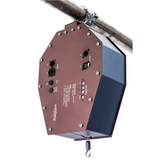 Winch 1
3 documents
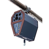 Winch 3
8 documents
Documents
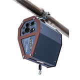 Winch 10
8 documents · 48 FAQs
Documents
Winch 10 and Winch 3 – FAQ
Important: This FAQ does not replace the manual. Read the manual and its safety information before installing, powering, operating or servicing the winch. Check www.wahlberg.dk for the most recent documentation. The manual revision number is printed at the bottom of each page of the manual.
Safety and use
What are the general safety precautions for the Winch 10 and Winch 3?
- The product is for professional use and presents risks for severe injury or death.
- Always warm up electronic equipment to room temperature before applying power.
- Isolate the product from power immediately if it is defective or shows signs of overload. Do not reapply power until repairs have been completed.
- Do not modify the product in any way not described in the manual.
- Refer any service operation not described in the manual to a qualified technician.
- Install only genuine Wahlberg parts.
How do I protect against injury when using the Winch 10 or Winch 3?
- Fasten the product securely to a fixed surface, rig or structure as described in the manual.
- Ensure that any supporting hardware can hold at least 10 times the weight of all the devices it supports.
- Block access below the work area whenever installing or servicing the product.
- Do not use the product to lift people or animals, and do not exceed the load limits.
- Do not use the product over the head of people.
- Only operate the winch when there is a clear view to the winch and the area beneath it.
- Before running the winch, ensure that the area beneath it is cleared to avoid risk of injury.
How do I protect against electric shock?
- Do not expose the product to rain or moisture.
- Use an AC power source with overload and ground (earth)-fault protection.
- Disconnect from AC power before servicing.
- The winch must be grounded (earthed).
What are the temperature and burn precautions for the Winch 10 and Winch 3?
- Do not operate the product if the ambient temperature (Ta) exceeds 40 °C (104 °F).
- The exterior of the product becomes warm during use. Avoid contact by persons and materials. Allow the product to cool for at least 10 minutes before handling.
- If the surface temperature of the Winch 10 / Winch 3 exceeds 70 °C (194 °F), there is a risk of damaging the winch.
Can the Winch 10 or Winch 3 be used outdoors?
No. The winch is intended for indoor use only. Do not expose it to rain, and store it indoors.
What is the Winch 10 / Winch 3 designed for, and what must not be done?
The winch is designed for lifting and lowering material at the weight and speed stated in the technical specifications. Any other use may result in a risk of injury of persons or equipment damage. Exceeding the load rating may cause failure of the equipment. The maximum load is 10 kg (22 lb) for the Winch 10 and 3 kg (6.7 lb) for the Winch 3.
- Use only approved rigging connectors to secure the load to the wire.
- Do not wrap the wire around the load, as this will damage the wire and result in a risk of injury or equipment damage.
- Do not modify the winch. For any modification of your winch, contact Wahlberg.
- It is the customer’s sole responsibility to comply with any relevant local laws, regulatory requirements and restrictions concerning the use of the winch.
Who should operate the Winch 10 / Winch 3?
The winch should only be operated by an experienced lighting desk operator, and only experienced DMX users should operate it. Contact Wahlberg for further information and education on the DMX protocol.
Before first use and transport
What should I do before using the Winch 10 or Winch 3 for the first time?
Protect the winch from physical shocks and vibration during storage. Before applying power:
- Check www.wahlberg.dk for the most recent documentation and technical information about the Winch 10 / Winch 3. Wahlberg user manual revisions are identified by the revision number at the bottom of each page.
- Carefully review the safety instructions in the manual.
- Check that the local AC mains power source is within the winch’s power voltage and frequency range.
- Install a Neutrik powerCON TRUE1 female power input connector on a suitable power cable. If using power from a mains power outlet, install a suitable power plug on the power cable.
How do I prepare the Winch 10 or Winch 3 for transport?
- Before transport, roll the wire up to the hard TOP limit so that a maximum of 5 cm (1.9 in) remains out of the winch. If the wire is slack, it may jump off the wire wheel during transport and cause damage to the winch.
- Protect the winch from physical shocks and vibration during transport.
- Use only the original packaging, flight case or pallet frame. Contact Wahlberg for enquiries regarding flight cases or pallet frames.
Installation
How must the Winch 10 or Winch 3 be mounted?
The winch must be either fastened to a flat surface such as a roof, or clamped to a truss or similar structure, in such a way that the wire exits downwards. Do not apply power to the winch if it is not securely fastened. If fastening to a flat surface, the supporting surface must be hard and flat. Check that the surface can support at least 10 times the weight of all winches and equipment installed on it.
How do I mount the Winch 10 or Winch 3 on a truss?
Warning: Use only the supplied rigging clamp and M12 bolt. The clamp must be screwed into the central hole in the winch’s mounting bracket using the supplied M12 washers and M12 locking-nut.
- Check that the rigging clamp is undamaged and that the rigging structure can support at least 10 times the combined weight of all winches and equipment to be installed on it.
- Use the supplied rigging clamp, or contact Wahlberg Motion Design for a replacement.
- Fasten the clamp to the winch with the supplied M12 bolt, nut and washers in the hole in the mounting clamp of the winch.
- Block access under the work area. Working from a stable platform, hang the winch on the truss with the wire downwards. Tighten the rigging clamp.
- Install a suitable safety cable through the clamp bracket when hanging overhead.
The manual’s photo on page 9 shows four winches clamped to a truss, with the safety cable marked.
How do I attach the load to the Winch 10 or Winch 3?
- The load must be mounted on the wire in a way that ensures it can never run into the winch.
- The load can be mounted using the supplied loading hook or any other hooks designed for lifting.
- The loading hook must have a minimum breaking load of at least 100 kg.
Does the Winch 10 or Winch 3 need a counterweight? Why won’t it run down?
Yes. Before running the winch, put a counterbalance on the wire. The winch has a slack detection device that stops the motor from moving down if the wire becomes loose. Without a counterweight attached to the wire hook, the winch will not work properly and will not run further down. The specifications list a minimum load of 0.45 kg (0.99 lb), and the manual’s quick start uses a counterweight of at least 0.45 kg (0.99 lb).
The winch will always run up if directed to do so, except if the TOP limit switch is unintentionally activated before the top position is reached. Slack detection has no influence on the ability to move up.
Power
What power cable and connectors does the Winch 10 / Winch 3 require?
- A power input cable with a Neutrik powerCON TRUE1 female cable connector for AC mains input.
- A Neutrik powerCON TRUE1 male cable connector for AC through, for daisy chaining.
- The cable must be rated 20 A minimum, have three conductors of 1.5 mm² (AWG 16) minimum conductor size, and an outer cable diameter of 6–16 mm (0.24–0.47 in).
- Cables must be heat resistant to 90 °C (194 °F) minimum.
- In the EU the cables must be approved or equivalent. In the USA: minimum hard usage type SJT or equivalent.
- If you install a power plug on the power cable, install a grounding-type (earthed) plug rated 20 A for USA and 16 A for Europe. Follow the plug manufacturer’s instructions.
What are the wire colours for the power plug?
| Wire colour | Conductor | Symbol | Screw (US) |
|---|---|---|---|
| Brown | Live | L | Yellow or brass |
| Blue | Neutral | N | Silver |
| Yellow/green | Ground (earth) | Ground (earth) symbol | Green |
If pins are not clearly identified, or if you have any doubts about proper installation, consult a qualified electrician.
What must I check before connecting the Winch 10 / Winch 3 to AC power?
- The winch must be grounded (earthed).
- The power distribution circuit must be equipped with a fuse or circuit breaker and ground-fault (earth-fault) protection.
- Socket outlets or external power switches used to supply the winch must be located near the winch and be easily accessible, so the winch can easily be disconnected from power.
- Check that the voltage range selector matches the local AC mains voltage before applying power. Do not apply AC mains power at any other voltage than specified on the winch’s serial number label.
What plugs does the Winch 10 / Winch 3 have?
The winch has 4 plugs. At the top are 2 DMX plugs: one for connecting DMX in and one for daisy chaining DMX to other devices. Below are a POWER in plug and a plug for daisy chaining power between multiple devices. Below those plugs are the voltage selector and the fuse (marked MAX 2A). The voltage selector must be set to the appropriate voltage before power is applied to the winch.
What should I check if the Winch 10 / Winch 3 does not react when power is connected?
- Check that the power plug is properly connected, both to the POWER IN plug on the winch and to the mains power plug.
- Check that the fuse is tightly screwed into the fuse cap, also if it has just been changed.
- Check that the fuse is intact. It can be replaced with a new 2.0 A fuse.
- Check that the voltage selector is set to the correct voltage.
How do I check and connect the powerCON TRUE1 connector?
Regularly check the condition of the powerCON TRUE1 connector system (cable connector and chassis) for clear signs of wear and tear. Through improper use and excessive force, the encoding lugs and guide slots can become so worn or damaged that the cable connector can be inserted the wrong way. When inserted the wrong way, the connector should not twist-lock into place. A cable connector inserted the wrong way could in some circumstances lead to contact between live wires and the grounding contact in the plug socket.
- When connecting, match the notch on the cable connector to the corresponding guide slot on the chassis.
- After inserting properly, twist the cable connector clockwise to lock.
- The proper twist-lock is achieved when the silvery tab is in the position shown in illustration C on page 31 of the manual, and an audible “click” is heard.
- Immediately unplug any connector that does not twist-lock correctly in place.
How do I install a powerCON TRUE1 female input connector on a power cable? (Appendix 2)
The manual refers to the original Neutrik instructions in Appendix 2 (pages 33–34). Key points from those instructions:
- The powerCON TRUE1 system is intended to supply power to an appliance and from an appliance to other equipment. It is to be installed by a qualified person only.
- VDE approval (EN 60320-1 / EN 60320-2-2): 250 V ac / 16 A. Cable types: H05VV-F3G 1.0 mm² (length max. 2 m), H05VV-F3G 1.5–2.5 mm², H07RN-F3G 1.5 mm².
- UL approval (UL 498 / CSA C22.2 No. 182.3): 250 V ac / 20 A. Cable types: SJTOW, SJOOW 3 x 12 AWG.
- Strain relief: white chuck. Cable outer diameter (O.D.) listed in Appendix 2: 6.0–12.0 mm. Note: the main text on page 10 states an outer cable diameter of 6–16 mm.
- Cable preparation as shown in Appendix 2: 20 mm, 8 mm, and PE 23 mm.
- Wiring, VDE: L brown, N blue, ground green/yellow. Wiring, UL: L black, N white, ground green.
- Slide the cable into the contacts and clamp with the screw using Torx size T8, torque value 0.7 Nm.
- Torque value 2.0 Nm for tightening the cable clamp, wrench size 13 mm (tool available: Art. No. HTAC).
- Important: align the chuck by positioning the nose into the keyway. Important: the black O-ring must be hidden to achieve IP protection.
- Caution: to ensure the protection category, do not expose the connection to bending forces, for example by attaching loads to the cable or leaving free-dangling cable windings.
- Safety warning: for safety and certification reasons the connector must be replaced in case of any broken parts or excessive wear and tear.
DMX connection and channels
How do I connect DMX to the Winch 10 / Winch 3?
A DMX 512 data link is required in order to control the winch via DMX. The winch has 5-pin XLR connectors for DMX data input and output. The pin-out on all connectors is pin 1 = shield, pin 2 = (–), pin 3 = (+). Pins 4 and 5 are not used in the Winch 10 / Winch 3 but are available for possible additional data signals as required by the DMX512-A standard.
- Connect the DMX data output from the DMX controller to the winch’s male 5-pin XLR DMX input connector (DMX 512 IN).
- Connect the DMX output of the winch to the DMX input of the next winch, and continue connecting output to input (DMX 512 OUT).
- Terminate the last winch on the link with a 120 Ohm resistor.
How many Winch 10 / Winch 3 units can be on one DMX link?
The common limit of 32 devices per daisy-chained link applies. If independent control of a winch is required, it must have its own DMX channels. Winches that are required to behave identically can share the same DMX channels. To add more winches or groups of winches when the limit is reached, add a DMX universe and another daisy-chained link.
What are the tips for reliable DMX data transmission?
- Use shielded twisted-pair cable designed for RS-485 devices. Standard microphone cable cannot transmit control data reliably over long runs. AWG24 cable is suitable for runs up to 100 meters (328 ft).
- Never split a DMX line without using an opto-isolated RS-485 splitter/amplifier.
- Terminate the link by installing a termination plug in the output socket of the last winch. The termination plug is a male XLR plug with a 120 Ohm, 0.25 Watt resistor soldered between pins 2 and 3. It “soaks up” the control signal so it does not reflect and cause interference. If a splitter is used, terminate each branch of the link.
What does the green DMX LED on the Winch 10 / Winch 3 mean?
The DMX lamp is the green LED next to the DMX selectors.
- Glows constantly: DMX connection is correct.
- Flashes: DMX signal is missing or wrongly connected.
How do I set the DMX address on the Winch 10 / Winch 3?
The DMX address, also known as the start channel, is the first channel used to receive instructions from the controller. It is set using the three DMX ADDRESS selectors on the winch (100., 10. and 1.). The selected address states from which channels on the lighting desk the winch is controlled. The address can be selected from 1 to 505. The Winch 10 / Winch 3 uses 7 DMX channels. For independent control, each winch must be assigned its own control channels.
What are the 7 DMX channels of the Winch 10 / Winch 3?
| DMX channel | Function | Description |
|---|---|---|
| 1 | Position rough | Controls the position of the winch, with the speed on channel 3. Works together with the fine position (channel 2). Rough and fine position are combined into a 16-bit channel. The rough position is the MSB. |
| 2 | Position fine | Controls the position of the winch, with the speed set on channel 3. Works together with the rough position (channel 1). The fine position is the LSB. |
| 3 | Speed | Controls the speed and defines the maximum speed of the winch. The winch runs with the set max speed but slows down when closing in on the wanted position. Also works as a main brake: the motor does not run unless the channel is set above 0 %. Can also be used to make soft and slow movements or fast and sudden movements. |
| 4 | Shift soft TOP limit | Controls the maximum top travelling height of the winch. See the soft TOP and BOTTOM limits section. |
| 5 | Shift soft BOTTOM limit | Controls the soft BOTTOM limit of the winch. See the soft TOP and BOTTOM limits section. |
| 6 | Find hard TOP limit, moving UP | Used to manually find the hard TOP limit. Controls the speed from 0–100 %. The winch starts to run up when channel 6 is set above 0 %. When the winch reaches the wanted TOP limit, the speed must be set to 0 % so that the motor stops. The TOP limit of the winch is then set to the position where the winch stopped. The soft TOP limit must always be near the motor-house. |
| 7 | Moving down | The winch starts to run down when the speed is set above 0 %. Can be used to manually move the winch down without using positioning. Does not change the TOP or BOTTOM limits. |
Attention: the positioning run in MODE 2 works only when the winch has been reset.
Control system block diagram
What does the block diagram of the control system show? (Appendix 3)
Appendix 3 of the manual (page 35) contains a block diagram of the control system of the winch. In text, it shows:
- Input/output plugs: power out (PowerCON TRUE1), AC mains power input (PowerCON TRUE1), DMX signal in (XLR 5 pole) and DMX signal out (XLR 5 pole).
- Power supply: converts 230/115 VAC to 27 VDC and supplies the controller.
- Controller: receives the DMX signal (control input DMX signal) and has a manual control BCD switch input.
- Travel range limits: a top limit switch is connected to the controller.
- Load measuring: underload (slack detection) and overload (electrical measurement) are connected to the controller.
- Motor: the controller supplies motor power, and a position measurement on the motor reports back to the controller.
Operation
Does the Winch 10 / Winch 3 have an emergency stop?
No. There is no dedicated emergency stop. The winch is controlled from a lighting desk, where it should always be set up with a button that sets the speed of the winch in operation to 0 %. Normally lighting desks have a “blackout” button that sets all signals to 0 %, and this will also cause the winch to stop. The user can also stop the winch by disconnecting it from the mains. After a power failure the start position of the winch needs to be reset before the winch can function again.
When must the Winch 10 / Winch 3 be reset?
The winch needs to be reset before the positioning MODE is possible. It can be reset manually or automatically. It must be reset each time its power supply has been disconnected.
How do I reset the Winch 10 / Winch 3 manually?
Manual reset is done in MODE 2 on DMX channel 6. When the winch is ready, the first thing to do is to reset it.
- Set DMX channel 6 to 30 %: the winch starts to roll up the wire.
- When the snap hook approaches the motor-house, reduce the speed by reducing the channel 6 input. High speed can damage the winch and wire.
- Let it run until the snap hook at the end of the wire reaches the motor-house.
The winch is now reset, and the TOP limit is at the built-in motor-house top (10 cm below). If you want a lower soft TOP limit, see the soft TOP and BOTTOM limits section.
Warning: When resetting the winch in MODE 2, it is important to decrease the speed as the snap hook closes in on the motor-house, otherwise the wire and winch can be damaged.
How does positioning work on the Winch 10 / Winch 3?
When the winch has been reset and the TOP limit is set, it can be used for positioning runs.
- The position is set on DMX channels 1 and 2 (rough and fine position). 100 % is the soft TOP limit and 0 % is the soft BOTTOM limit.
- The speed is set on DMX channel 3, where 100 % is the fastest and 0 % is the slowest.
- The winch does not run unless channel 3 is set above zero. Channel 3 therefore also works as a main brake.
What does the green LED next to the MODE selector mean?
- Fast flashing: the winch needs to be reset before it can be used.
- Slow flashing: the winch’s load is moving towards the set position.
- Steady light: the set position has been reached and the motor has stopped.
How do I get started with the Winch 10 / Winch 3? (Quick start from the manual’s cheat sheet)
- Place or rig the winch in a truss or similar with a minimum clearance of 2–3 m (3–6 ft) below.
- Put on a counterweight on the winch hook, minimum 0.45 kg (0.99 lb).
- Set the DMX start address to 001 and the MODE to 2.
- Apply DMX from a lighting desk, preferably with manual faders.
- Make sure the 7 channels are patched from DMX channel 1 to 7.
- Pull all channels to 0 %.
- Apply power to the winch. The DMX lamp should be lit, and the mode lamp should be flashing.
- Pull channel 6 to 20 %: the winch starts pulling the wire.
- When the wire is at the hard TOP limit (pulled into the winch), stop the winch (set channel 6 to 0 %). The winch has now found its TOP position and is ready to drive with position control.
- Pull channel 1 (position) to 95 %.
- Pull channel 3 (speed) to 20 %. The winch starts to move down, with 20 % speed, to the 95 % up-position.
- Pull channel 1 (position) to 80 %. The winch starts to move down, with 20 % speed, to the 80 % up-position.
- Pull channel 1 (position) to 90 %.
- Pull channel 3 (speed) to 50 %. The winch starts to move UP again, with 50 % speed, and stops 1 meter before the top.
What is the duty cycle of the Winch 10 / Winch 3?
The Winch 10 and Winch 3 should not be operated at a duty cycle higher than 30 % for longer periods of time. The duty cycle is the fraction of a period where the motor is active. Example from the manual: a maximum duty cycle of 30 % (10 min ON / 23 min OFF) means the motor may not be active more than 10 minutes every 33 minutes. After 10 minutes of ON, the motor must be OFF for 23 minutes.
How do I set the soft TOP and BOTTOM limits on the Winch 10 / Winch 3?
The TOP limit needs to be reset, automatically or manually, before the winch can be used for positioning runs. The soft TOP and BOTTOM limits can be regulated to fit your needs.
- The TOP limit is reset manually with DMX channel 6. When the soft TOP limit is reset, it should always be set near the motor-house.
- The winch has a pre-set soft BOTTOM limit that is always 10 meters from the TOP limit. If the TOP limit is set far from the motor-house and the soft BOTTOM limit is not adjusted, the winch will still run 10 m (33 ft) down and eventually run out of wire. This activates the slack detection, and the winch will not go any further down.
- To avoid running out of wire, adjust the max travel to the soft TOP and BOTTOM limits on DMX channels 4 and 5.
- Examples from the manual’s diagram: channel 4 at 66 % is about 2 m from the top position. Channel 5 at 10 % is about 1 m from the bottom position.
Attention: If the two ranges overlap, the soft TOP limit overrules the soft BOTTOM limit. The winch will move down to that position but will be unable to be moved with normal positioning, because the operating range has been reduced to 0.
| DMX ch. 4 | Distance from the soft TOP limit | DMX ch. 5 | Distance from the soft BOTTOM limit |
|---|---|---|---|
| 0 % | 0 m (0 ft) | 0 % | 0 m (0 ft) |
| 10 % | 0.3 m (1.0 ft) | 10 % | 1 m (3.3 ft) |
| 20 % | 0.6 m (2.0 ft) | 20 % | 2 m (6.6 ft) |
| 30 % | 0.9 m (3.0 ft) | 30 % | 3 m (9.8 ft) |
| 40 % | 1.2 m (4.0 ft) | 40 % | 4 m (13.1 ft) |
| 50 % | 1.5 m (5.0 ft) | 50 % | 5 m (16.4 ft) |
| 60 % | 1.8 m (6.0 ft) | 60 % | 6 m (19.7 ft) |
| 70 % | 2.1 m (7.0 ft) | 70 % | 7 m (23.0 ft) |
| 80 % | 2.4 m (8.0 ft) | 80 % | 8 m (26.2 ft) |
| 90 % | 2.7 m (9.0 ft) | 90 % | 9 m (29.5 ft) |
| 100 % | 3.0 m (10.0 ft) | 100 % | 10 m (32.8 ft) |
How do I run several Winch 10 / Winch 3 units in synchronized movements?
The best result is achieved by using a fading 16-bit position. The motors deviate slightly in performance, so some have a slightly higher maximum speed than others. Fading the position from one position to another over a certain amount of time, like fading conventional light, lets multiple winches follow the same fade curve.
- Set the speed channel to 100 to gain the highest possible speed.
- Assign the position channel as a 16-bit channel with MSB and LSB.
- Make the speed of the fade slower than the maximum speed, so the motors have enough speed to follow the fade curve.
If the fade is too fast, the winches move at maximum speed and you will see the difference in motor speed. If the fade is too slow, the winches move – stop – move – stop when the position changes, giving a discontinuous movement.
How do I re-calibrate the overload on the Winch 10 / Winch 3?
Warning: Re-calibrating the overload affects the safety mechanisms of the winch. Violation of the maximum overload can cause a dangerous situation with risk of serious injury or death.
The winch is set to enter overload mode if it is loaded with more than the nominal load. The overload is a safety feature to ensure that the winch cannot lift more than what is safe. Overload detection is based on the motor current, which is affected by the efficiency of the gear. As the gear’s efficiency changes with usage, the overload may need re-calibrating. It is essential to test that the overload is correct at regular inspections. The overload can be re-calibrated to lower values as follows:
- Ensure at least 1.5 m clearance below the winch.
- Load the winch with the desired overload threshold weight + 10 % (max. 11 kg total for Winch 10 and max. 3.3 kg total for Winch 3).
- Set the DMX channels to 999. Attention: when the mode is set to 9, the winch will start moving.
- Then set the MODE to 9.
The winch will now run down several times. When the winch has moved back to the TOP limit, the overload has been re-calibrated. Ensure that you change the DMX channel and MODE away from 999 and 9 after re-calibration. Re-calibrating is only for service and tests.
Service and maintenance
What safety rules apply when servicing the Winch 10 / Winch 3?
- Read the safety information before servicing the winch.
- Disconnect the winch from AC mains power and allow it to cool down for at least 10 minutes before handling.
- Refer any service operation not described in the manual to a qualified service technician.
- The interval of inspections should be determined according to the frequency of use and the working scenario of the winch.
- Signs of malfunction or poor operation should always lead to an inspection of the winch. Take the winch out of operation until the error is eliminated.
- Only parts ordered at or approved by Wahlberg should be used in the winch, to ensure product function and stability. Contact Wahlberg to inquire about spare parts.
- If the wire runs at an angle, performance degrades and the wire wears down faster, which shortens the lifetime of the wire significantly. Wire damage caused by mounting the winch at an angle is not covered by the product warranty. Figure 1 in the manual (page 23) illustrates the winch mounted at different angles: wire angle 0° and wire angle 10° (two examples).
What is the maintenance plan for the Winch 10 / Winch 3?
The results of all regular inspections must be documented and kept available by the owner. The written result of the last inspection must be kept available at the site of operation, for example by an inspection sticker on the winch showing the date of the inspection, the basis of the inspection and the name of the inspector.
Before every use, and at least weekly while the winch is in use (every time when rigging the winch and before running it):
- Check that the winch is safely and correctly installed/mounted.
- Check that the winch’s load and LEDs are visible from the operating station.
- Check the entire length of the wire rope for bends, crushed areas, broken or cut cord, corrosion and other damage.
- Check all safety devices (slack detection, hard TOP limit).
- Check that the wire is wound neatly on the drum.
- Check the wire ferrule crimp and thimble.
- Check that the load is securely mounted.
Monthly, and at least every month while the winch is in use:
- Check the mounting clamp and loading hook for damage and proper fastening.
- Change damaged parts according to the manual.
- Check that the overload detection is correct.
Every 12 months: the winch must be inspected by a specialist.
Every 48 months: the winch should be inspected by an authorised expert.
What is on the inspection checklist for the Winch 10 / Winch 3?
Use the checklist before each use, each month and so on, in line with the maintenance plan.
| Check | Type |
|---|---|
| Installed / mounted correct | Inspection |
| Load and LEDs visible for the operator | Inspection |
| Entire wire length OK | Inspection |
| Slack detection | Functional test |
| Hard TOP limit | Functional test |
| Overload | Functional test |
| Wire ferrule crimp | Inspection |
| Wire thimble | Inspection |
| Load mounted safely | Inspection |
| powerCON TRUE1 | Inspection |
What should I check before each use? (Cheat sheet)
- Check that the winch is safely and correctly installed/mounted.
- Inspect the entire length of the wire rope for bends, damage and wear, cut cords, corrosion and abuse.
- Inspect the wire ferrule crimp and thimble for damage, wear, corrosion or abuse.
- Secure that the load is safely attached and weighs max. 10 kg (22 lb) for the Winch 10 and max. 3 kg (6.7 lb) for the Winch 3.
- Check all limit switches.
- Check the slack detection device.
Warning: Do not use the winch if any damage or error is found.
Does Wahlberg offer on-site service for the Winch 10 / Winch 3?
Yes. On-site service and maintenance can be provided by Wahlberg Motion Design, giving owners access to Wahlberg Motion Design’s expertise and product knowledge. Contact Wahlberg Motion Design for details.
What wire does the Winch 10 use, and how long does it last?
Winch 10 lifting wire: 2 mm (5/64 in) 7x7 galvanized steel wire (EN 12385-4). Minimum breaking load: 310 kg (3040 N / 683 lb). Wire safety factor: >10.
Maximum expected wire lifetime for the Winch 10, running up and down:
- At 2.5 kg (5.5 lb) load: up to 80,000 cycles.
- At 5.0 kg (11 lb) load: up to 20,000 cycles.
- At 10 kg (22 lb) load: up to 15,000 cycles.
The expected lifetime of the wire depends on the load, the travel length and the duty cycle. Wires are subject to wear and tear over the life of the product, and the extent depends heavily on operating conditions and environment, so it is impossible to specify precisely whether and to what extent the wire performance will be affected. The wire should be inspected long before these numbers are reached, checked for damage and replaced if necessary.
What wire does the Winch 3 use, and how long does it last?
Winch 3 lifting wire: 2.3 mm coated 1.5 mm (5/64 in) 7x7 stainless steel wire (EN 12385-4). Minimum breaking load: 130 kg (1275 N / 287 lb). Wire safety factor: >10. Maximum expected wire lifetime: Pending.
What should I do if the wire on the Winch 10 / Winch 3 is damaged, stuck or does not wind properly?
If the wire gets damaged, stuck or has problems winding on and off, the wire and wire roll-up need to be inspected:
- Disconnect the power.
- Remove the 6x M3 hexagonal socket screws on one of the middle plates.
- Take off the loose middle plate to look into the winch. Figure 2 in the manual (page 24) shows the Winch 10 (left) and Winch 3 (right) with a removed middle plate.
- If the wire is not tight around the wire-wheel, or it is bundled up inside, it needs to be unravelled. This is done by manually unravelling and loosening the wire and pulling it out of the winch. It can be necessary to remove the other middle plate to work it out of the winch properly.
- If the wire is bent or damaged, it must be replaced. See the wire discard criteria and the wire change procedure in this FAQ.
- If the wire is okay, it must be rolled on again.
- Mount the middle plate on the winch using the 6x M3 hexagonal socket screws and tighten them slightly.
Remember to always make a counterbalance in the wire when running the winch. According to the manual, a missing counterbalance is often the reason why the wire gets loose and tangled up.
When must the wire of the Winch 10 / Winch 3 be discarded?
When the wire rope is exposed, these guidelines can be used. If any of the discard criteria is reached, the winch must immediately be taken out of service and the wire replaced before the winch is used again. Discard the wire rope when:
- The overall diameter of the rope is reduced by 8 %, or the outer wires have lost 33 % of their diameter through wear. Measure the reduction on a portion of the rope that has been subjected to abrasion and stresses, relative to a portion subjected to stresses but not abrasion, for example portions near the drum or anchorage.
- There is evidence of considerable plastic wear or surface embrittlement.
- The diameter of the rope has suddenly reduced, or the lay length has suddenly increased or decreased.
- There is evidence of severe corrosion, like chain pitting.
- There is any evidence of internal corrosion in the rope. This can be recognized by slackness of outer wires due to the internal wires corroding away.
- The rope has been subjected to mechanical damage, crushing, kink, bends, bird cage and similar.
- The core of the rope has collapsed.
- The rope has been subjected to a high temperature or heat due to fire.
- The rope has been subjected to severe shock load or overload due to an accident with the winch.
When using a calliper to measure the wire rope diameter, measure from crown to crown, not from valley to valley (Figure 3 in the manual, page 25, shows a correct and an incorrect calliper position).
How is the wire changed on the Winch 10 / Winch 3?
If the wire has any damage, the winch must not be used until the wire has been replaced. This can be done following the instructions below, or by Wahlberg. Contact Wahlberg Motion Design for information regarding approved spare parts and questions about the procedure. The manual (pages 26–30) has photos of the stages.
- Roll off the wire: Set the winch to MODE 8 (manual roll down). Pull down on the wire to deactivate the slack detection. Continue pulling until all the wire has been rolled off the winch. Cut off the old wire using a steel rope cutter.
- Disconnect the power.
- Remove the 6× M3 hexagonal socket screws on each middle plate on the winch.
- Take off the two loose middle plates to access the wire mount.
- Remove the end frame and plate by removing the four M4 hexagonal socket screws.
- Remove the four hexagonal spacers and the two bolts holding the TRAFO-plate.
- Remove the two bolts and nuts holding the mounting plate and the TRAFO-plate together.
- Take the PVC tube out of the transformer plate.
- Carefully lift off the transformer plate and tilt it. Ensure that none of the wires and plugs is damaged during this operation.
- Take out the wire-wheel and cut off the wire-eye of the old wire, allowing the old wire to be removed.
- Cut off 10.6 m of 2 mm 7x7 galvanized steel wire rope (approved by Wahlberg).
- Put the new wire through the ‘top stop’ and through the hole in the wire-wheel.
- Form an eye with the new wire and a ferrule (approved by Wahlberg), using the old eye as a template.
- Place the eye over the axle of the wire-wheel.
- Mount the wire-wheel back on the winch. You might need to take out the slack detection to make it fit in.
- Ensure that the spacing washer for slack detection is installed.
- Assemble the winch by placing the transformer plate on top of the wire-wheel. Ensure that the ‘top stop’ and slack detection are correctly mounted.
- Tighten the bolts and nuts for the mounting bracket. Check that you use the right bolts, by ensuring that the bolt goes through the nut and self-locks.
- Mount the four hexagonal spacers and the two bolts holding the transformer plate.
- Ensure that the ‘top stop’ and slack detection spring are correctly mounted.
- Hereafter the wire must be rolled on. See “How do I apply (roll on) the wire?” below.
- When the wire end is approx. 30 cm away from the ‘top stop’, stop the wire roll up. Place the top bead (wire stop) on the wire and make an eye using thimble and ferrule (approved by Wahlberg). Ensure to use appropriate swaging or crimping tools. Attention: the wire stop is essential for the function of the winch. Forgetting the spring will damage the winch.
- Roll up the last bit of the wire.
- Mount the middle plates on the winch again and fasten each with the six 3 mm hexagonal socket screws. Tighten them slightly.
How do I apply (roll on) the wire on the Winch 10 / Winch 3?
Warning: Be careful not to touch the power supply inside the winch, as it is exposed. This can cause an electric shock and damage you and the winch. Be careful not to get fingers, hair, clothes or similar caught in the wire-wheel as it turns. This can damage you and the winch.
- Set the MODE to MODE 0 (neutral), to make sure the motor does not start inadvertently when the power is connected.
- Connect the power.
- Set the DMX start address to zero (000).
- Set the MODE to manual up (MODE 7).
- Set the speed on the DMX address. The suggested address is 100, which is a fine, slow speed that is easy to follow.
- Using a glove, hold the wire firmly to ensure it is rolled up tightly around the wire drum. Attention: keep the wire stretched tight until it is all rolled up, to ensure that the wire is rolled up tightly around the wire-wheel. Make sure not to bend or damage the loose wire as it rolls on.
- When the wire has rolled on all the way, disconnect the power or set the speed (DMX start address) to zero (000).
When the wire has been applied to the winch again, it is good practice to run it up and down a couple of times before assembling it again. Remember always to make a counterbalance in the wire when running the winch, as a missing counterbalance is often the reason why the wire gets loose and tangled up in the first place.
No questions match. Try another word or clear the search.
Based on Wahlberg Motion Design User Manual 241.805.017, dated 2025-11-18. The manual covers the Winch 10 (item no. 241) and the Winch 3 (item no. 243). Where the manual gives separate values for the two models, this FAQ does the same. Where a value is written “Winch 10 / Winch 3”, it applies to both.
Contact: Wahlberg Motion Design, Jens Juuls Vej 1, 8260 Viby J, Denmark. Telephone +45 86 18 14 20. Email sales@wahlberg.dk.
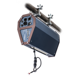 Winch 10 Cable
8 documents
Documents
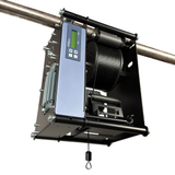 Winch 25
5 documents
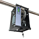 Winch 25 Curtain
5 documents
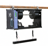 Winch 25 Double
5 documents
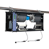 Winch 25 Double Cable
5 documents
 Winch 50
4 documents · 64 FAQs
Winch 50 Series – FAQ
Important: This FAQ does not replace the manual. Read the manual and its safety information before installing, powering, operating or servicing the winch. Check www.wahlberg.dk for the most recent documentation. The manual revision number is printed at the bottom of each page of the manual.
Safety and use
What are the general safety precautions for the Winch 50 Series?
- The product is for professional use and presents risks for severe injury or death.
- Always warm up electronic equipment to room temperature before applying power.
- Isolate the product from power immediately if it is defective or shows signs of overload. Do not reapply power until repairs have been completed.
- Do not modify the product in any way not described in the manual.
- Refer any service operation not described in the manual to a qualified technician.
- Install only genuine Wahlberg Motion Design parts.
How do I protect against injury when using the Winch 50 Series?
- Fasten the product securely to a fixed surface, rig or structure as described in the manual.
- Ensure that any supporting hardware can hold at least 10 times the weight of all the devices it supports.
- Block access below the work area whenever installing or servicing the product.
- Do not use the product to lift people or animals, and do not exceed the load limits.
- Do not use the product over the head of people.
- When the product is installed and may not be used for some time, inspections and maintenance according to the manual must always be followed.
How do I protect against electric shock?
- Do not expose the product to rain or moisture.
- Use an AC power source with overload and ground (earth)-fault protection.
- Disconnect from AC power before servicing.
- The winch must be grounded (earthed).
What are the temperature and burn precautions for the Winch 50 Series?
- Do not operate the product if the ambient temperature (Ta) exceeds 40 °C (104 °F).
- The exterior of the product becomes warm during use. Avoid contact by persons and materials. Allow the product to cool for at least 10 minutes before handling.
- If the surface temperature exceeds 70 °C (194 °F), there is a risk of damaging the winch.
Can the Winch 50 Series be used outdoors?
No. The Winch 50 Series is intended for indoor use only. Do not expose it to rain.
What is the Winch 50 Series designed for, and what must not be done?
The winch is for stage use, mainly in theatres, shows and concerts. It is designed for lifting and lowering material at the weight and speed stated in the technical specifications. Any other use may result in a risk of injury of persons or equipment damage. Exceeding the load rating may cause failure of the equipment.
- The lifting capacity is 50 kg (110.2 lb).
- Use only mounting connectors approved by Wahlberg Motion Design to secure the load to the winch.
- Do not modify the product. For any modification, contact Wahlberg Motion Design.
- It is the customer’s sole responsibility to comply with any relevant local laws, regulatory requirements and restrictions concerning the use of the product.
Who should operate the Winch 50 Series?
The winch should only be operated by an experienced DMX-controlled lighting desk operator. The lighting desk must be programmed according to the manual, so the winch stops when the speed is set to 0 %. Contact Wahlberg Motion Design for further information and education on the DMX protocol. Manual operation of the winch is only intended for installation, service and tests.
When does the control system allow the motor to run?
The control system ensures that the motor is only powered when:
- The DMX signal is reliable.
- The mode, position and speed control are set correctly.
- The drum position is within the span of the soft and hard limits.
- There is no overload.
Models and specifications
Which models does the Winch 50 Series include?
| Item no. | Model |
|---|---|
| 245.3 | Winch 50 |
| 245.4 | Winch 50 Pilewind |
| 246.5 | Winch 50 Double |
| 246.4 | Winch 50 Double +Power and Cat5 |
What are the load, height and speed of the Winch 50 Series?
- Lifting capacity: 50 kg (110.2 lb).
- Lifting height: 12.5 m (41 ft) for 245.3, 246.4 and 246.5. For 245.4: 9.7 m (31.8 ft) on the wire version and 4 m (13.1 ft) on the power version.
- Lifting speed: 3–100 cm/s (1.2–39.4 in/s) for 245.3, 246.4 and 246.5. 1–45 cm/s (0.4–17.7 in/s) for 245.4.
- Minimum load: 5 kg (11 lb) for 245.3, 246.4 and 246.5. No minimum load is needed for 245.4.
What are the power, motor and connector specifications?
- Power supply: 208–240 V AC, 50–60 Hz.
- Power consumption: 825 W (4.0–3.5 A).
- Power inlet: Neutrik powerCON TRUE1 NAC3PX-TOP (F/M).
- DMX control signal: DMX 512 1990 + DMX512A, 6 channels used.
- DMX connection: 5-pole XLR (F/M).
- Motor: 230 V AC, 0.55 kW.
- Noise emission: ~50 dB.
- Ambient temperature: 5–40 °C (32–104 °F) as listed in the specifications.
- Mounting clamp: 4× slim eye coupler, 42–52 mm (2 in).
What are the dimensions and weight?
| Item no. | Dimensions (L×W×H) | Own weight |
|---|---|---|
| 245.3 | 345 × 298 × 464 mm (13.6 × 11.7 × 18.3 in) | 29.1 kg (64.2 lb) |
| 245.4 | 345 × 298 × 464 mm (13.6 × 11.7 × 18.3 in) | Not listed in the manual |
| 246.5 | 797 × 298 × 464 mm (31.4 × 11.7 × 18.3 in) | 47.5 kg (104.7 lb) |
| 246.4 | 893 × 274 × 455 mm (35.2 × 10.8 × 17.9 in) | 53 kg (116.8 lb) |
What is included in the package?
- 1× Winch 50 / Winch 50 Double / Winch 50 Double +Power and Cat5.
- 1× powerCON NAC3FX-W-TOP female plug for power cable.
- 1× powerCON NAC3FX-W-TOP female plug for power input to bar (246.4 only).
- 1× powerCON NAC3MX-W-TOP male plug for power output from bar (246.4 only).
- 1× User manual.
- 1× Cheat sheet.
Before first use and transport
What should I do before using the Winch 50 Series for the first time?
Protect the winch from physical shocks and vibration during transportation and storage. Before applying power:
- Check www.wahlberg.dk for the most recent documentation and technical information about the product. User manual revisions are identified by the revision number at the bottom of each page.
- Carefully review the safety information on page 2 of the manual.
- Check that the local AC mains power source is within the power voltage and frequency ranges.
- Install the provided Neutrik powerCON TRUE1 NAC3FX-W-TOP power connector on a suitable power cable. If using power from a mains power outlet, install a suitable power plug on the power cable.
How do I prepare the Winch 50 Series for transport?
- Roll the wire up and fix it with a cable tie or an elastic cord. If the wire is slack, it may jump off the drum during transport and damage the winch.
- Protect the winch from physical shocks and vibration during transportation.
- Use only the original packaging or a flight case. Contact Wahlberg Motion Design for enquiries regarding flight cases or pallet frames.
Installation
How must the Winch 50 Series be mounted?
The winch must be either fastened to a flat surface such as a roof, or clamped to a truss or similar structure, so that the wire exit points downwards. Do not apply power if the product is not securely fastened.
- The supporting surface must be hard and flat, and able to support at least 10 times the weight of all products and equipment installed on it.
- Use only the supplied rigging clamps.
- Make sure the wire exit point is straight downwards to maintain the expected lifetime of the wire.
How do I mount the Winch 50 Series on a truss?
- Check that the rigging clamps are undamaged and that the rigging structure can support at least 10 times the combined weight of all products and equipment to be installed on it.
- Block access under the work area. Working from a stable platform, hang the product on the truss with the mounting clamp upwards. Tighten the rigging clamp.
- Use the 2 supplied slim couplers on the top plate. Both must be used, because the load is not evenly distributed across the product.
- Install suitable safety cables when the product is hanging overhead, and verify that this complies with either EN 60598-2-17:2018 section 17.7.4 or BGV C1/DGUV 17.
How do I attach the load to the Winch 50 Series?
- The load must be mounted on the wire so that it can never run into the winch.
- The load can be mounted using a suitable loading hook designed for lifting.
- The loading hook must have a minimum breaking load of at least 500 kg.
Does the Winch 50 Series need a counterbalance?
Yes. Before running the winch, put a counterbalance on the wire, because the slack detection switch will otherwise activate and stop the winch. The minimum load is 5 kg (11 lb) for 245.3, 246.4 and 246.5. No minimum load is needed for 245.4.
What is wire fleet?
Because of the way the winch rolls up the wire, the point where the wire comes out of the winch changes depending on how much wire has been rolled out. The wire moves approx. 80 mm sideways from the hard TOP limit to the hard BOTTOM limit. The 245.4 has no wire fleet.
Power
What power cable and connectors does the Winch 50 Series require?
- A power input cable with a Neutrik powerCON TRUE1 NAC3FX-W(-TOP) cable connector for AC mains input.
- The cable must be rated 20 A minimum, have three conductors of 1.5 mm² (AWG 16) minimum conductor size, and an outer cable diameter of 6–16 mm (0.24–0.47 in).
- Cables must be heat resistant to 90 °C (194 °F) minimum.
- In the EU the cables must be <HAR> approved or equivalent. In the USA: minimum hard usage type SJT or equivalent.
- If you install a power plug on the power cable, install a grounding-type (earthed) plug rated 20 A for USA and 16 A for Europe. Follow the plug manufacturer’s instructions.
- To install a powerCON TRUE1 connector, follow the original Neutrik instructions in the appendix to the manual (page 43).
What are the wire colours for the power plug?
| Wire colour | Conductor | Symbol | Screw (US) |
|---|---|---|---|
| Brown | Live | L | Yellow or brass |
| Blue | Neutral | N | Silver |
| Yellow/green | Ground (earth) | Ground (earth) symbol | Green |
If pins are not clearly identified, or if you have any doubts about proper installation, consult a qualified electrician.
What must I check before connecting the Winch 50 Series to AC power?
- The product must be grounded (earthed).
- The power distribution circuit must be equipped with a fuse or circuit breaker and ground-fault (earth-fault) protection.
- Socket outlets or external power switches used to supply the product must be located near the equipment and be easily accessible, so it can easily be disconnected from power.
- Check that the voltage range on the serial number label matches the local AC mains voltage. Do not apply AC mains power at any other voltage than specified.
What happens when the Winch 50 Series is powered on?
The display shows a start-up sequence with the product name, then the software version, then a description of how to enter the menu. Before the winch is ready to be controlled by DMX, channel 4 must be re-enabled. After that it is ready to be operated.
How do I check and connect the powerCON TRUE1 connector?
- Regularly check the connector system (cable connector and chassis) for clear signs of wear and tear.
- Through improper use and excessive force, the encoding lugs and guide slots can become so worn or damaged that the cable connector can be inserted the wrong way. When inserted the wrong way, it should not twist-lock into place.
- A cable connector inserted the wrong way could in some circumstances lead to contact between live wires and the grounding contact in the plug socket.
- Listen for the “click” when performing the twist-lock. Immediately unplug any connector that does not twist-lock correctly in place.
How does the lifting wire power and Ethernet work on the Winch 50 Double +Power and Cat5 (246.4)?
- The lifting wire requires a power input through a Neutrik powerCON NAC3FX-W-TOP cable connector.
- Power through: 16 A / 240 V AC, 2×1.5 mm² (AWG 16). Signal through: two twisted pairs Cat5 (100 Mbit/s).
- Socket outlets or external power switches used to supply the lifting wire attachment must be located near the winch and be easily accessible.
- Check that the voltage matches the range specified for the lifting wire before applying power. Do not apply power at any other voltage than specified in the manual.
- To install the powerCON TRUE1 cable connector, follow the original Neutrik instructions in the appendix to the manual (page 43).
DMX connection and channels
How do I connect DMX to the Winch 50 Series?
A DMX 512 data link is required to control the winch via DMX. The winch has 5-pin XLR connectors for DMX data input and output. The pin-out on all connectors is pin 1 = shield, pin 2 = (–), pin 3 = (+). Pins 4 and 5 are not used in normal operation and are available for additional data signals as required by the DMX512-A standard. They can also be used to feed back the actual position of the winch, but then the port is not suitable for daisy chaining.
- Connect the DMX data output from the DMX controller to the male 5-pin XLR DMX input connector (DMX 512 IN).
- Connect the DMX output of the product to the DMX input of the next product, and continue connecting output to input (DMX 512 OUT).
- Terminate the last product on the link with a 120 Ohm resistor.
How many Winch 50 Series units can be on one DMX link?
The common limit of 32 devices per daisy-chained link applies. If independent control of a winch is required, it must have its own DMX channels. Products that are required to behave identically can share the same DMX channels. To add more products or groups of products when the limit is reached, add a DMX universe and another daisy-chained link.
What are the tips for reliable DMX data transmission?
- Use shielded twisted-pair cable designed for RS-485 devices. Standard microphone cable cannot transmit control data reliably over long runs. AWG24 cable is suitable for runs up to 100 meters (328 ft).
- Never split a DMX line without using an opto-isolated RS-485 splitter/amplifier.
- Terminate the link by installing a termination plug in the output socket of the last winch. The termination plug is a male XLR plug with a 120 Ohm, 0.25 W resistor soldered between pins 2 and 3. If a splitter is used, terminate each branch of the link.
What do the LEDs on the Winch 50 Series mean?
- DMX LED (green, above the display), glows constantly: DMX connection is correct.
- DMX LED flashes: the DMX signal is missing or wrongly connected.
- Error LED off: no errors on the winch.
- Error LED on (red): an error is detected. See the error description on the display. Reset an error by setting DMX channel 4 to 0 %.
How do I set the DMX address on the Winch 50 Series?
The DMX address, also known as the start channel, is the first channel used to receive instructions from the controller. It is set in the menu under DMX ADDRESS, in the range 1–506. For independent control, each product must be assigned its own control channels.
What are the 6 DMX channels of the Winch 50 Series?
| DMX channel | Function | Description |
|---|---|---|
| 1 | Position rough (MSB) | Controls the position of the drum, with the speed on channel 3. The rough position (MSB) and fine position (LSB) form a 16-bit channel. Using only the rough position may be enough for some applications. |
| 2 | Position fine (LSB) | See channel 1. |
| 3 | Speed | Controls the speed and defines the maximum lifting and lowering speed. Can also work as a brake, since the motor does not run in positioning mode unless the channel is set above 0 %. |
| 4 | Enable motor (50–55 %) | Safety channel. Values between 50 % and 55 % make the product run. All other values stop the motor, reset errors and save the current position before a power down. Leave this channel at 0 % before a regular power down. |
| 5 | Setting the soft TOP limit | At 2 % or more the drum moves up until it reaches the hard TOP limit, at variable speed (2 % = low speed, 100 % = full speed). There is a 3 second delay from activation to movement, to reduce accidental limit overwrites. |
| 6 | Setting the soft BOTTOM limit | At 2 % or more the drum moves down until it reaches the hard BOTTOM limit, at variable speed (2 % = low speed, 100 % = full speed). There is a 3 second delay from activation to movement. |
When channel 5 or 6 returns to 0 %, the drum returns to the current wanted position given by channels 1 and 2, provided the unit has a valid soft BOTTOM limit and the speed on channel 3 is not zero.
Can the Winch 50 Series report its position?
Yes, with the POS OUT setting in the advanced menu. The position feedback outputs a DMX signal on pins 1, 4 and 5 of the DMX in/out plugs. All values are zero except the feedback, which is located at the DMX address of the device. If the winch has start channel 73, the 16-bit feedback is at channels 73 and 74.
- OFF: no output.
- SCALE: 16-bit scaled feedback, 0,0 at the bottom and 255,255 at the top.
- DIV 4: 16-bit raw feedback divided by 4, 0,0 at the bottom and TAC RANGE divided by 4 at the top. For a 10 meter span this is roughly 77,104.
- 32BIT: 32-bit raw feedback, 0,0,0,0 at the bottom and TAC RANGE at the top. For a 10 meter span this is roughly 0,1,53,161.
Emergency stop
Does the Winch 50 Series have an emergency stop?
It can be configured with an optional emergency stop switch. By default, the emergency stop is NOT enabled. The DMX control from a lighting desk should always be set up with a button that sets the speed of the winch in operation to 0 %. Normally lighting desks have a “blackout” button that sets all intensity channels to 0 %, and this will also stop the winch when assigned correctly.
How do I connect and enable the emergency stop switch?
The switch is connected to the male 4-pole XLR connector on the winch. Pin 1 and pin 4 must be powered with 12–15 V DC to enable operation of the winch.
| Pin | Connection |
|---|---|
| 1 | GND |
| 2 | Not connected |
| 3 | Not connected |
| 4 | 12–15 V DC |
- Enter the menu navigation mode.
- Change E STOP from OFF to ON.
- Connect the winch to power, DMX and the emergency stop switch. It can then be controlled from the lighting desk.
To get the full functionality of the emergency stop, a wire has to be plugged in inside the winch, as described in the manual. The emergency stop power supply and plug are available from Wahlberg Motion Design.
What happens when the emergency stop is activated?
The red Error LED lights and the display shows ‘EMERGENCY STOP PRESSED’ and the current start channel of the unit.
Hard and soft limits
What is the difference between the hard and soft limits?
- Soft limits are entirely software controlled and limit the working range for a given application or show. They are saved automatically when a setup procedure is started with DMX channel 5 or 6.
- Hard limit switches set the maximum and minimum travel distance of the winch. They make a click sound when pressed or released, and the display shows when one is activated.
- The hard limits are factory pre-set to stop 3 cm below the winch and have a travel length of 12.5 m.
How do I set the soft TOP and BOTTOM limits?
The soft TOP limit must always be set before the soft BOTTOM limit.
- Set DMX channel 5 to 30 % and wait 3 seconds. The winch moves up towards its hard TOP limit. Set channel 5 to 0 % at the wanted position. This is now the soft TOP limit.
- Set DMX channel 6 to 30 % and wait 3 seconds. The winch moves down towards its hard BOTTOM limit. Set channel 6 to 0 % at the wanted position. This is now the soft BOTTOM limit.
When both are set, the internal range (TAC RANGE) is calculated. It is the number of encoder pulses between the soft TOP and soft BOTTOM limits, which correlates to the 0 % and 100 % positions on channels 1 and 2.
Warning: There must be at least 2 rounds left on the drum when the winch is adjusted for the soft BOTTOM limit. Also make sure the load cannot cause injury or hit any obstacles in the moving range.
How do I adjust the hard limits?
Caution: Do not set the hard TOP limit where the load can run into the winch itself, as this will damage the winch.
- Put the winch in manual mode while adjusting the limits.
- Locate the hard limit switch box, the black box just in front of the fan.
- Loosen the two screws holding the lid.
- Loosen the middle screw.
- Adjust the hard BOTTOM limit by turning the screw with a 1 next to it.
- Adjust the hard TOP limit by turning the screw with a 2 next to it.
- When adjustments are done, tighten the middle screw again.
- Mount the lid with the two screws again.
It is not advisable to adjust the hard TOP limit closer to the winch than 3 cm. For software versions before 503.001.012, the stopping distance was longer, and the hard TOP limit should not be closer to the winch than 10 cm.
Operation
How do I get started with the Winch 50 Series? (Quick start from the cheat sheet)
- Place or rig the winch with a minimum of 2 meters of clearance below.
- Load the wire with a minimum load of 5 kg (11 lb). No load is needed for 245.4.
- Connect the mains and emergency switch (if enabled), and make sure the error LED is no longer glowing red. The winch turns on and the display shows the start-up message.
- Set the DMX start address to 1 and apply DMX from a lighting desk, preferably with manual faders. Make sure the 6 channels are patched from DMX channel 1 to 6. Pull all channels to 0 %.
- Set DMX channel 4 between 50 % and 55 %. The motor is now enabled and the winch can run.
- Set DMX channel 5 to 30 % and wait 3 seconds. The winch moves up towards its hard TOP limit. Set channel 5 to 0 % to stop when desired or at the hard TOP limit. This position is now the soft TOP limit.
- Set DMX channel 6 to 30 % and wait 3 seconds. The winch moves down towards its hard BOTTOM limit. Set channel 6 to 0 % to stop when desired or at the hard BOTTOM limit. This position is the soft BOTTOM limit.
- Set DMX channel 1 to 100 % and DMX channel 3 to 20 %. The winch moves with 20 % speed to the 100 % position.
- Set DMX channel 1 to 90 % and DMX channel 3 to 50 %. The winch moves with 50 % speed to the 90 % position.
- Before shutting down, set DMX channel 4 to 0 % to save the current position. When the winch powers on, it recalls its position and limits and is ready to position.
How do I save the position before shutting down?
Set DMX channel 4 to 0 % before a regular power down. This saves the current position, and the unit is ready to position when powered on. If it is not saved before shutdown, the soft TOP limit must be set again when the unit is powered on.
What is the duty cycle of the Winch 50 Series?
The winch should not be operated at a duty cycle higher than 30 % for longer periods of time. The duty cycle is the fraction of a period where the motor is active. Example from the manual: a maximum duty cycle of 30 % (10 min ON / 23 min OFF) means the motor may not be active more than 10 minutes every 33 minutes. After 10 minutes of ON, the motor must be OFF for 23 minutes.
How does the load affect the speed?
The load impacts the minimum speed the winch can operate at. At heavy loads, the minimum speed up must be increased to a point where the winch can still move. With a light load and high minimum speeds, the winch might have problems finding its position. In that case, lower the minimum speeds. The minimum speed is adjusted in the menu.
How do I run several Winch 50 Series units in synchronized movements?
The best result is achieved by using a fading 16-bit position. The motors deviate slightly in performance, so some have a slightly higher maximum speed than others. Fading the position from one position to another over a certain amount of time, like fading conventional light, lets multiple winches follow the same fade curve.
- Set the speed channel to 100 % to gain the highest possible speed.
- Assign the position channel as a 16-bit channel with MSB and LSB.
- Make the speed of the fade slower than the maximum speed, so the motors have enough speed to follow the fade curve.
If the fade is too fast, the winches move at maximum speed and you will see the difference in motor speed. If the fade is too slow, the winches move – stop – move – stop when the position changes, giving a discontinuous movement.
Errors and troubleshooting
What should I check if the Winch 50 Series does not start?
- Display shows nothing: check that the winch is connected to mains power and that the fuse in the winch is intact.
- DMX lamp is blinking: check the DMX signal.
What should I do if the wire is not wound up on the drum correctly?
Manually lower the wire totally off the drum, while inspecting that the wire comes out of the winch evenly. Afterwards, roll the wire back onto the drum and reset the top position.
What does “Not in Pos” or “NO MOVEMENT DETECTED” on the display mean?
- “Not in Pos”: the winch cannot move to its position. This usually occurs when the load is high. Go into the menu and increase the minimum speed up.
- “NO MOVEMENT DETECTED”: the winch continuously does not measure any movement when trying to move. Check that nothing has caught, and if not, go into the menu and increase the minimum speed up.
What happens after a power failure?
The winch stops at power failure. When the power is re-established, the winch must be reset before it is ready to use. It is advisable to set all DMX channels to 0 % before the power is re-established.
How do I reset an error?
Set DMX channel 4 to 0 %. When the Error LED lights red, there is also an error description on the display. When an error occurs, the control system shuts down the motor and issues an error code.
What do the error codes mean?
“Power cycle” below means: unplug the power, wait 30 seconds, and apply power again. Consult an authorized service technician if the failure keeps coming.
| Code | Error message | Cause | Remedy |
|---|---|---|---|
| 1 | OVERCURRENT | Inverter overcurrent. The momentary output current is permanently exceeded. | The motor load may be too high. |
| 2 | OVERVOLTAGE | Overvoltage in the DC link. | The input AC voltage might be too high. |
| 3 | EARTH FAULT | Possible insulation failure in internal wiring or motor. | Power cycle. |
| 8 | SYSTEM FAULT | Internal system error. | Power cycle. |
| 9 | UNDER VOLTAGE | Undervoltage in the DC link. | The input AC voltage might be too low. |
| 10 | INPUT PHASE | Input line phase is missing. | Check supply voltage quality, external fuses and cable. |
| 11 | OUTPUT PHASE | Missing current in one or more motor phases. | Power cycle. |
| 13 | UNDER TEMP <-10C | The ambient temperature is below -10 °C. | Warm up electronic equipment to room temperature before applying power. |
| 14 | DRIVE OVER TEMP | Inverter overheat. The power electronics temperature is too high. | Cooling is insufficient: ambient temperature too high, insufficient air circulation, dirty air grate or defective fan. Let the drive cool down before restarting. |
| 15 | MOTOR STALLED | Motor stall protection has tripped. | The load may be too high. |
| 16 | MOTOR OVER TEMP | Possible motor overheating detected by the internal frequency inverter. | The load or the ambient temperature may be too high. |
| 17 | MOTOR UNDERLOAD | Motor underload protection has tripped. | Power cycle. |
| 22 | EEPROM CHECKSUM | Malfunction in the inverter memory. | Power cycle. |
| 25 | MICROCONTROLLER | Timer reset of the watchdog. | Power cycle. |
| 27 | BACK EMF | Motor was running during start-up. | Power cycle. |
| 34 | INTERNAL BUS | Possible communication error in the equipment. | Power cycle. |
| 35 | APPLICATION | Possible firmware error in the equipment. | Power cycle. |
| 41 | IGBT OVER TEMP | Inverter overheat. The power electronics temperature is too high. | See error 14. |
| 51 | EXTERNAL FAULT | Possible digital input fault. | Power cycle. |
| 53 | FIELD BUS | Possible internal communication error in the inverter. | Power cycle. |
| 57 | IDENTIFICATION | Motor identification run has failed. | Power cycle. Repeating the identification may only be required if the setting has been lost or performance issues are seen at full load. Consult Wahlberg Motion Design. |
| Other | UNKNOWN FAULT | Unknown or not applicable for the application. | Power cycle. |
What does the block schematic of the control system show?
Appendix 6 of the manual (page 45) contains a block schematic of the control system. In text, it shows:
- Input/output plugs: power in 208–240 V AC and power out (powerCON TRUE1), emergency stop, DMX signal in and out (XLR 5 pole). 245.4 and 246.4 also have power in and Cat5 in for the bar (powerCON TRUE1, etherCON), and power out and Cat5 out for the bar.
- Power supply and motor controller, with a controller receiving the DMX signal and a manual control input.
- Travel range limits: top hard limit and bottom hard limit.
- Load measuring: slack detection (underload) and overload (electronic).
- Drive train: motor, gear, encoder and slip rings.
Service and maintenance
What safety rules apply when servicing the Winch 50 Series?
- Read the safety information before servicing the winch.
- Disconnect the winch from AC mains power and allow it to cool down for at least 10 minutes before handling.
- Refer any service operation not described in the manual to a qualified service technician.
- The interval of inspections should be determined according to the frequency of use and the working scenario of the winch.
- Signs of malfunction or poor operation should always lead to an inspection of the winch. Take the winch out of operation until the error is eliminated.
- Only parts ordered at or approved by Wahlberg Motion Design should be used. Contact Wahlberg Motion Design to inquire about spare parts.
- If the wire runs at an angle, performance degrades and the wire wears down faster, which shortens the lifetime of the wire significantly. Wire damage caused by mounting the winch at an angle is not covered by the product warranty.
What is the maintenance plan for the Winch 50 Series?
The results of all regular inspections must be documented and kept available at the company. The written result of the last inspection must be kept available at the site of operation, for example by an inspection sticker on the winch showing the date of the inspection, the basis of the inspection and the name of the inspector.
Before every use, and at least weekly while the winch is in use (every time when rigging the winch and before running it):
- Check that the winch is safely and correctly installed/mounted.
- Check that the winch’s load and LEDs are visible from the operating station.
- Check the entire length of the wire for bends, crushed areas, broken or cut cord, corrosion and other damage.
- Check all safety devices (slack detection, limit switches, emergency stop).
- Check that the wire is wound neatly on the drum.
- Check the wire ferrule crimp and thimble.
- Check that the load is securely mounted.
Monthly, and at least every month while the winch is in use:
- Check the mounting clamps for damage and proper fastening.
- Change damaged parts according to the manual.
- Check that the overload detection is working.
Every 12 months: the winch must be inspected by a specialist.
Every 48 months: the winch should be inspected by an authorised expert.
What is on the inspection checklist for the Winch 50 Series?
Use the checklist before each use, each month and so on, in line with the maintenance plan.
| Check | Type |
|---|---|
| Installed / mounted correct | Inspection |
| Load and LEDs visible for the operator | Inspection |
| Entire wire length OK | Inspection |
| Slack detection | Functional test |
| Overload | Functional test |
| Emergency stop | Functional test |
| Wire is wound neatly around the drum | Inspection |
| Wire ferrule crimp | Inspection |
| Wire thimble | Inspection |
| Load mounted safely | Inspection |
| powerCON TRUE1 | Inspection |
What should I check before each use? (Cheat sheet)
- Check that the winch is safely and correctly installed/mounted.
- Inspect the entire length of the wire rope for bends, damage and wear, cut cords, corrosion and abuse.
- Inspect the wire ferrule crimp and thimble for damage, wear, corrosion or abuse.
- Check that the load is safely attached and weighs max. 50 kg (110.2 lb).
- Check safety functions (limit switches, slack detection and emergency stop).
- Check that the wire is wound neatly on the drum.
- Make sure that the operator has visual confirmation of all possible movements of the winch at all times.
Warning: Do not use the winch if any damage or error is found.
Does Wahlberg offer on-site service for the Winch 50 Series?
Yes. On-site service and maintenance can be provided by Wahlberg Motion Design, giving owners access to Wahlberg Motion Design’s expertise and product knowledge. Contact Wahlberg Motion Design for details.
What wire does the Winch 50 Series use?
- 245.3, 245.4 (wire version), 246.4 and 246.5: 3 mm (1/8 in) 19x7 galvanized steel wire (EN 12385-4). Minimum breaking load: 590 kg (5786 N / 1301 lb).
- 245.4 (power version): 6.5 mm (1/4 in) 8x17 galvanized steel wire (EN 12385-4). Minimum breaking load: 2230 kg (21869 N / 4916 lb).
- Wire safety factor: >10. Wire angle: none.
How long does the wire last?
The expected lifetime of the wire depends on the load, the travel length and the duty cycle. Wires are subject to wear and tear over the life of the product, and the extent depends heavily on operating conditions and environment, so it is impossible to specify precisely whether and to what extent the wire performance will be affected.
When must the wire of the Winch 50 Series be discarded?
When the wire is exposed, these guidelines can be used. If any of the discard criteria is reached, the winch must immediately be taken out of service and the wire replaced before the winch is used again. Discard the wire when:
- The overall diameter is reduced by 8 %, or the outer wires have lost 33 % of their diameter through wear. Measure the reduction on a portion that has been subjected to abrasion and stresses, relative to a portion subjected to stresses but not abrasion, for example portions near the drum or anchorage.
- There is evidence of considerable plastic wear or surface embrittlement.
- The diameter has suddenly reduced, or the lay length has suddenly increased or decreased.
- There is evidence of severe corrosion, like chain pitting.
- There is any evidence of internal corrosion. This can be recognized by slackness of outer wires due to the internal wires corroding away.
- The wire has been subjected to mechanical damage, crushing, kink, bends, bird cage and similar.
- The core of the wire has collapsed.
- The wire has been subjected to a high temperature or heat due to fire.
- The wire has been subjected to severe shock load or overload due to an accident with the winch.
When using a calliper to measure wire diameter, measure from crown to crown, not from valley to valley.
No questions match. Try another word or clear the search.
Based on Wahlberg Motion Design User Manual 245.805.014, dated 2026-01-07. The manual covers the Winch 50 (item no. 245.3), the Winch 50 Pilewind (245.4), the Winch 50 Double (246.5) and the Winch 50 Double +Power and Cat5 (246.4). Where the manual gives separate values for the models, this FAQ does the same.
Contact: Wahlberg Motion Design, Jens Juuls Vej 1, 8260 Viby J, Denmark. Telephone +45 86 18 14 20. Email sales@wahlberg.dk.
 Winch 50 Pilewind
5 documents
 Winch 50 Double
4 documents
 Winch 50 Double + Power and CAT5
4 documents
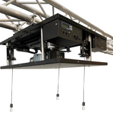 Triple Winch
1 document
 Pulley Wheel
No documents listed
 Wires for Winches
No documents listed
 Winch 25 Curtain Mounting Bracket
1 document
 Winch 25 Mounting Bracket
1 document
 Winch 25 Double Mounting Bracket
No documents listed
 Winch 50 Pilewind Mounting Bracket
2 documents
Rotators
 DMX Rotator
6 documents
Documents
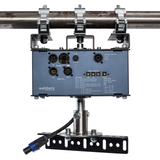 DMX Rotator with Power Outlet
6 documents
Documents
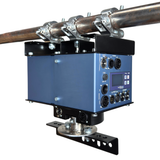 DMX Rotator with Power and CAT5e
4 documents
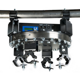 DMX Giga Rotator with Power and CAT5
4 documents
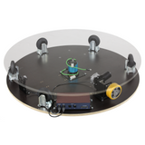 Revolving Stage Ø1,2m
3 documents
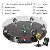 Revolving Stage Components
3 documents
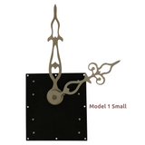 DMX Clockwork
4 documents
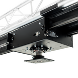 Rotracktor
5 documents
Track Systems
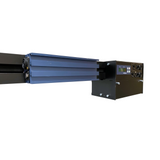 Manipulator
4 documents
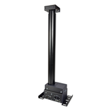 Lifting Column
4 documents
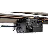 Track Runner with Cogwheel
8 documents
Documents
Track Runner with Friction Wheel
8 documents
Documents
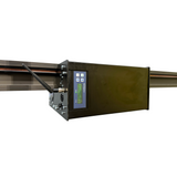 Mega Track Runner
4 documents
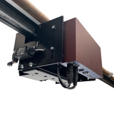 Track Runner for Joker95
2 documents
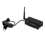 Wireless DMX Transmitter
2 documents
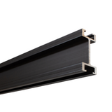 Track Profile
2 documents
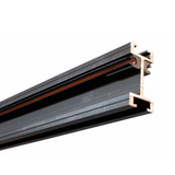 Track Profile with Conductor Rail
2 documents
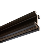 Track Profile with Tooth Rack
2 documents
 Track Profile with Tooth Rack and Conductor Rail
2 documents

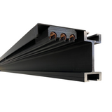 Track Profile with External Power
2 documents
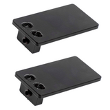 End Cover Set
No documents listed
 Passive Runner
3 documents
 Passive Runner - Heavy Duty
3 documents
 End Stop Set
No documents listed
 Side Mount for Mega Track Runner
1 document
 Cable Runner
1 document
 Connection Bracket
No documents listed
 Track Alignment Tool
1 document
 Eye Bolt Bracket
2 documents
 Slim Coupler Bracket
No documents listed

 Floor Rail Cart
4 documents
Floor Rail System
 Wireless Floor Rail Kit
1 document
 Floor Rail Endstop Set
2 documents

 Floor Rail
2 documents
 Cable Chain
2 documents
 Cart Endstop Set
2 documents
 Floor Rail Motor Console
2 documents
 Floor Rail Encoder Console
2 documents
 Main Plate (Floor Rail)
2 documents
 Floor Rail Battery Pack
2 documents
 Support Wheel
No documents listed
 DC Motor Controller (300W)
No documents listed
 RC Battery Charger 2x3A
2 documents
 Powercon Cable
No documents listed
 DMX Cable
No documents listed
Roll Downs
 Mini Roll Down
5 documents
 Medium Roll Down Slow
4 documents
 High-speed Roll Down
4 documents
 DMX Snow Machine
4 documents
 Flightcase for Roll Down
No documents listed
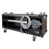 Curtain Sniffer
4 documents
Projector Shutters
 DMX Projector Shutter
1 document
 DMX Projector Shutter with Button
1 document
 DMX Projector Shutter Button
No documents listed
 Small Shutter Flap
No documents listed
 Mega Shutter Flap
No documents listed
RC Platforms
 RC Platform 70x70 cm Standard
2 documents
 RC Platform 70x70 cm Offroad
1 document
 RC Platform 2x1m Onroad Ø125mm Wheels
3 documents
 RC Platform 2x1m Offroad Ø200mm Wheels
3 documents
 RC Platform 2x1m Offroad Ø260mm Wheels
3 documents
 RC Platform Expansion Plate 2x1m
3 documents
 RC Platform 70x70cm Components
3 documents
 RC Platform 2x1m Components
3 documents
 RC Control Box 2x15Ah
2 documents
 RC Control Box 2x26Ah (incl. Transmitter)
2 documents
 RC Battery Charger 2x10A
2 documents
 Motor Console 125mm Wheel
2 documents
 Motor Console 200mm Wheel
2 documents
 340W Motor Console 125mm Wheel
3 documents
 340W Motor Console 200mm Wheel
3 documents
 340W Motor Console 260mm Wheel
3 documents
 Castor Wheel 125mm
2 documents
 Castor Wheel 200mm
2 documents
 Castor Wheel 260mm
No documents listed
Motors
 AC Motor Controller 550 W
4 documents
 AC Motor Controller 3000 W
4 documents
 DC Motor Controller (120W)
4 documents
 Actuator Compact
1 document
 Actuator Large
1 document
 DMX Motor Unit
4 documents
 DC Motor 17 RPM
No documents listed
 DC Motor 60 RPM
No documents listed
 DC Motor 110 RPM
No documents listed
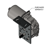 90° Mounting Clamp for DC Motor
1 document
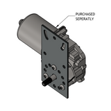 Mounting Clamp for DC Motor
1 document
Accessories
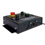 Control Box
1 document
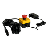 Emergency Stop 12VDC
No documents listed
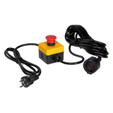 Emergency Stop 230VAC
No documents listed
 Flightcase
No documents listed
No products match. Try another word or category.
